 |
 10-10-2007, 09:24 AM
|
#1
|
|
Moderator
Join Date: Jul 2007
Posts: 700
|
Hi all,
I suspect a problem with my VHF antenna. I suspect the problem is self-inflicted, that is to say I possibly did something bad while climbing the mast a few weeks back. I have two VHF units on board, both routed to the same antenna via a coax cable switcher, but I appear to have very limited range on either of them. I suspect it's the antenna at the masthead or the cabling running to it rather than the cable switcher but of course I need a way of testing all possibilities.
What's the best/standard way of testing whether I have a good connection between my radio and my masthead antenna? Normally in the land-line comms world (which I'm more familar with) I'd set up a tone generator and climb the mast with a detector to see where it came out, or if it was an electrical circuit I'd try the same with a dummy load and a multimeter, but VHFs aren't really my bag.
Del
__________________
|

|

|
|
10-10-2007, 10:11 AM
|
#2
|
|
Admiral
Join Date: Oct 2004
Posts: 3,067
|

Quote:
Originally Posted by delatbabel

Hi all,
I suspect a problem with my VHF antenna. I suspect the problem is self-inflicted, that is to say I possibly did something bad while climbing the mast a few weeks back. I have two VHF units on board, both routed to the same antenna via a coax cable switcher, but I appear to have very limited range on either of them. I suspect it's the antenna at the masthead or the cabling running to it rather than the cable switcher but of course I need a way of testing all possibilities.
What's the best/standard way of testing whether I have a good connection between my radio and my masthead antenna? Normally in the land-line comms world (which I'm more familar with) I'd set up a tone generator and climb the mast with a detector to see where it came out, or if it was an electrical circuit I'd try the same with a dummy load and a multimeter, but VHFs aren't really my bag.
Del
|
Hi Del ,
A few steps to check first :-
I will come back with a diagram or something .
In the mean time do you have a Multimeter - need the ohm meter to check continuity and any short between the centre core of the coax and the outer braid.
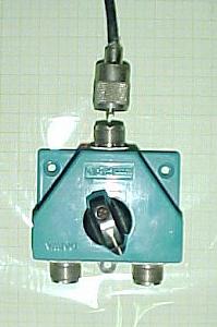
1. Unscrew the coax cable that goes to the mast from the 2 way switch >> then turn the switch to position for the 1st VHF>> then switch your multimeter to check the ohm reading>> then place one probe into the empty centre core hole on the switch , at the same time place the other probe on the outer metal surround of the centre hole == there should be no reading.
2. then turn the switch to position for the 2nd VHF>> then switch your multimeter to check the ohm reading>> then place one probe into the empty centre core hole on the switch , at the same time place the other probe on the outer metal surround of the centre hole == there should be no reading.
If you have no readings on steps 1. an 2. then you at least know that the coax cables between the radios and the 2 way are OK.
If you do not want go up the mast, you might want to make up an emergency VHF antenna which will tell you if your coax or antenna on top of the mast is OK or not - it will also be an antenna which you can store for a day when the mast head antenna is not working.
You will need a length of RG 8 thin coaxial cable sufficient to run from the top of your 2way switch to your push pit rail or higher. Then you will need a PL 259 plug (like the one in the picture for connecting to the top of your 2way switch , Then if you have an old metal measuring tape- cut off 17 3/4 " (inches) solder the centre core of the coax to the piece tape, Then with insulating tape - tape the stub antenna facing skywards to the aft rail or somewhere higher (make sure the antenna is isolated from any metal, eg the rail. )
Then arrange to speak to someone on a free channel to test both VHFs.
A very very useful site regarding Soldering the PL 259 :-
http://www.seed-solutions.com/gregordy/Ama.../SolderCoax.htm
Good Luck
Richard
__________________
__________________

|
|
|
|
|
10-10-2007, 12:59 PM
|
#4
|
|
Admiral
Join Date: Oct 2004
Posts: 3,067
|
Quote:
Originally Posted by svjacaranda
|
Hi Chuck ,
I was going on the assumption that both VHFs were functioning well before Del did something.
So the initial process was to eliminate coax or connection faults. Once these are dealt with and transmission is regained, then the reading for SWR can be established. However, if by chance the SWR reading is poor. then you will still require to go back to the basics. Luckily marine VHF radio if installed correctly with appropriate fittings and materials (including the most important - The correct Marine VHF antenna) will function well on 5 watts and a bit better on 25 watts without a SWR meter.
Richard
__________________
|
|
|
|
|
10-10-2007, 06:06 PM
|
#5
|
|
Ensign
Join Date: Sep 2007
Posts: 34
|
Thanks Richard - Your point about checking all the connectors and coax first makes the most sense.
Cheers
Chuck
__________________
|
|
|
|
|
10-10-2007, 10:59 PM
|
#6
|
|
Admiral
Join Date: Oct 2004
Posts: 3,067
|
Hi Del again,
I remembered over night that KISS is better. An easier emergency VHF antenna to make up instead of the one using a length of metal measuring tape is this one :-
1. length of RG 8 (thin) coax cable - sufficient to run from the top of the "2way switch" to the spreader where you have blocks for flag halyards.
2. 1 x PL259 plug
3. 30" (75cm)of around 30lb nylon fishing line
4. Insulating tape or if you have - 3M splicing tape.
Method : a. Attach the PL 259 to the Coax. as per previous instructions.
b. Strip 17 3/4 " (inches or 451mm) off the outer pvc cover from the other end of the coax then strip off 17 3/4" of braid that has been revealed , leaving just the plastic covered strand wire.
c. Now tie the fishing line to the coax below where the outer pvc was removed - at the other end of the fishing line tie a knot forming an eye.
d. Now tape the fishing line to the coax from where it was tied to the coax to where the coax terminates - tape the end so that water cannot get in.
Connect : plug in the PL 259 into the top of the 2way switch - take the flag halyard attach through the eye in the fishing line - haul up the antenna to the spreader block.
Test transmission on both VHFs. you may find that this simple emergency antenna will work as
well as the commercial job !
Richard
__________________
|
|
|
|
|
10-11-2007, 06:46 AM
|
#7
|
|
Moderator
Join Date: Jul 2007
Posts: 700
|
Thanks for all the help guys. I'll take the trusty multimeter on board with me this weekend (actually I think it's still on board) and if necessary I'll go up the mast and repair/fit the antenna. I prefer having the sticky-uppy-bit (technical term there) up the top of the mast rather than a jury rig one because I'm often sailing on the edge of my VHF limit off shore so need the extra range.
|
|
|
|
|
10-11-2007, 06:59 AM
|
#8
|
|
Admiral
Join Date: Oct 2004
Posts: 3,067
|
Quote:
Originally Posted by delatbabel
Thanks for all the help guys. I'll take the trusty multimeter on board with me this weekend (actually I think it's still on board) and if necessary I'll go up the mast and repair/fit the antenna. I prefer having the sticky-uppy-bit (technical term there) up the top of the mast rather than a jury rig one because I'm often sailing on the edge of my VHF limit off shore so need the extra range.
|
The second version described is as good as many commercial antennas - worth having one rolled up as an emergency spare.
Richard
__________________
|
|
|
|
|
10-13-2007, 11:24 AM
|
#9
|
|
Moderator
Join Date: Jul 2007
Posts: 700
|
Well, I've done most of what is suggested. I have verified that the switcher is working, that there is the expected (minimal) amount of impedance going back from the switcher to the VHF units, and that there are no shorts between the switcher and the masthead. I have found a couple of cable joins between the switcher and the masthead, one around the back of the nav table and one just under the base of the mast where there is a kind of junction box gathering together the various cables that do go up the mast.
What I plan to do tomorrow is to disconnect the coax from the cable switcher and stick a dummy voltage across the line that should be going to the mast. I can then test at various points whether that voltage is actually going up there. So questions:
a. does this sound like a reasonable approach?
b. assuming I stick, say, 1.2 volts across the coax cable at the cable switcher (I can generate that easily from a AA rechargeable battery), what's a reasonable voltage drop that I should be experiencing at the masthead, given working quality cabling and joins, etc?
c. I noticed today that some of the interconnecting cabling is not in fact RG-8 but rather RG-58. Is that a problem? I also note that Whitworths don't actually sell RG-8 as VHF antenna cable, but instead sell RG-213.
|
|
|
|
|
10-14-2007, 12:59 AM
|
#10
|
|
Admiral
Join Date: Oct 2004
Posts: 3,067
|
Quote:
Originally Posted by delatbabel
We I have found a couple of cable joins between the switcher and the masthead, one around the back of the nav table and one just under the base of the mast where there is a kind of junction box gathering together the various cables that do go up the mast.
b. assuming I stick, say, 1.2 volts across the coax cable at the cable switcher (I can generate that easily from a AA rechargeable battery), what's a reasonable voltage drop that I should be experiencing at the masthead, given working quality cabling and joins, etc?
c. I noticed today that some of the interconnecting cabling is not in fact RG-8 but rather RG-58. Is that a problem? I also note that Whitworths don't actually sell RG-8 as VHF antenna cable, but instead sell RG-213.
|
Answering c. first, The transmission coax mentioned are different :-
RG- 8 - 52 ohms - Velocity factor of 66%
RG- 58 - 53.5 ohms - Velocity factor of 66%
RG- 213 - 50 ohms - Velocity factor of 66%
The best coax in terms of VF is RG - 8 foam --- 52 ohms
In terms of least DB loss because length of cable is RG 213
To get the best out of transmission the fatter the central wire in the cable the better- however,
this may mean that the outside diameter of the coax makes it difficult to thread it to the mast head. I do not know what the effect of having a mixture of different coax transmission cable will have on the marine VHF 156 MHz freq. range, I GUESS not approved by the boffins.
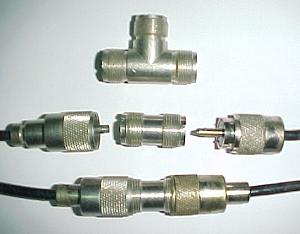
You mention a couple of cable "joins" between the Switch and Masthead. The only way Coax cable should be joined is using a double female connecter between 2 male PL 259s.
Here's a picture I put together - note the top item is a three way female connecter.
Voltage drop is not what you are looking for but rather DB loss over the length of the coax.
The usual problem to look for, is where the the insulating braid is in contact with the central transmission wire - the test is to make sure they are not in contact using your ohm meter. Another fault to look for is water ingress into the coax - 1st at the masthead where it connects to the antenna and anywhere where the cable is "joined".
__________________
|
|
|
|
|
04-03-2011, 04:22 AM
|
#11
|
|
Ensign
Join Date: Mar 2009
Posts: 13
|
I'm trying to troubleshoot a baffling VHF performance issue on my Beneteau sail boat. I am not a radio expert and my only available test gear is a Fluke multimeter, so my testing is limited to ohms rather than dB. I recently replaced my ICOM 502 with a new Ray 218 and have very poor performance. The ICOM also had poor performance, with max range of much less than 1 mile, despite the antenna mounting at 16m above the water.
Raymarine told me it was the antenna, so I replaced the old Banten masthead antenna with a stainless steel Shakespeare 4200. No improvement was heard, but I noticed the old VHF cable was corroded and blackened, possibly from a lightning strike. I therefore replaced the old mast VHF cable with 17m of new RG-8 and high quality PL259 connectors. I am pretty sure they are well terminated and read the page mentioned above ( http://www.seed-solu.../SolderCoax.htm). When the cable is connected to the antenna, I am measuring open circuit at the foot of the mast after I terminated the mast cable with the PL259. The splice to the cable to the VHF at the nav station is made with a 2-way female to female PL259 connector. This cable that runs from the foot of the mast inside the boat headlining back to the VHF is a thinner cable (maybe RG-58?), but looks well terminated and corrosion free - I could not measure a short.
However, the VHF performance / range is still very poor. Transmission range on high power is at best half a mile, and RX is maybe even less. I am getting a lot better performance from my handheld Standard HX850S, so am currently out of ideas. Any help gratefully received.
__________________
2005 Beneteau Oceanis 423 Clipper
|
|
|
|
|
04-03-2011, 11:13 AM
|
#12
|
|
Admiral
Join Date: Oct 2004
Posts: 3,067
|
I understand that you have a Ray 218 - maybe the best way to check this radio out is to remove the Shakespeare from the mast, beg borrow or steal sufficient RG 58 cable, PL259 fittings to either end of the RG 58, connect the pl 259s to the antenna and the radio. Hoist the antenna to the highest point possible -- apply 12vdc to the radio, open channel 16 ask for a radio check - IF your are tranceiving, change channels to say 68 and ask for a radio check.
Even with this jury rig you should be able to tranceive at 20 NM - if it works replace the antenna to the top of the mast and you should be able to work 35nm on 25 watts.
__________________
|
|
|
|
|
04-03-2011, 12:49 PM
|
#13
|
|
Moderator/Wiki Sysop
Join Date: Apr 2008
Home Port: Samos
Vessel Name: S/Y Thetis
Posts: 559
|
It seems to me that your problem is one or more mismatches along the cable and/or connectors. A mismatch causes part of the RF wave to be reflected back to the transmitter rather then to propagate to the antenna. This can not be detected by a multimeter since it is only the high frequency wave that is reflected and not DC low frequency AC. The correct measurement of the SWR (standing wave ratio) caused by mismatches is done by a specially equiped oscilloscope called TDR (time domain reflectometer). With this instrument one can detect the reflection and its position along the transmission line. However a TDR is expensive and not readily available but a cheap SWR meter is available from West Marine.
Using this inexpensive SWR meter and some elimination as described by MMNETSEA you can locate the troubled connection and/or cable.
Good luck.
 : Mediterranean, Black Sea, Atlantic |
|
|
|
|
12-02-2011, 10:27 AM
|
#14
|
|
Ensign
Join Date: Dec 2011
Home Port: Canarias
Posts: 1
|
You may use your handheld VHF for testing the antenna.
Most of them have a SMA connector.
You can buy a adapter from SMA to PL259.
Take care there is a reversed SMA connector very similar, but with a missing center pin.
You can compare the output with 1 Watt.
Wilhelm
__________________
__________________
I want to buy ICOM M503/DSC 100 for SRC Funkkurs
|
|
|
|
|
|
Currently Active Users Viewing This Thread: 1 (0 members and 1 guests)
|
|
|
 Posting Rules
|
You may not post new threads
You may not post replies
You may not post attachments
You may not edit your posts
HTML code is Off
|
|
|
|
 Recent Threads
 |
|
|
|
|
|
|
|
|
|
|
|
|
|
|
|
|
|
|
|
|
|
|
|


 Linear Mode


