 |
 10-11-2010, 12:48 PM
|
#1
|
|
Lieutenant
Join Date: Jan 2005
Posts: 97
|
I have a stainless steel waterlock which looks like just a vertical cylinder about 10 inches tall and 10 inches high. After two efforts to cure its leak by getting it rewelded, it is no better, it leaks slightly at the lower weld. The off-the-shelf versions are either too small ie smaller than the one I have (I am not sure how you are supposed to work out how much water they should hold)or too big to fit into the engine room. So I am thinking of getting one made of grp
I would rather know what they look like inside before I cut it open ! Does anyone know ? Is it empty, is there just a baffle, is it complicated ? Help, please
John
__________________
__________________

|

|

|
 10-11-2010, 01:17 PM
|
#2
|
|
Admiral
Join Date: Oct 2004
Posts: 3,067
|

Quote:
Originally Posted by steelfan

I have a stainless steel waterlock which looks like just a vertical cylinder about 10 inches tall and 10 inches high. After two efforts to cure its leak by getting it rewelded, it is no better, it leaks slightly at the lower weld. The off-the-shelf versions are either too small ie smaller than the one I have (I am not sure how you are supposed to work out how much water they should hold)or too big to fit into the engine room. So I am thinking of getting one made of grp
I would rather know what they look like inside before I cut it open ! Does anyone know ? Is it empty, is there just a baffle, is it complicated ? Help, please
John
|
hello John,
The initial description of this "Waterlock" !0" tall and 10" High is a little difficult to comprehend -- I guess that one of the measurements refers to the width of the outer cylinder???
A photo would be useful. Again guessing regards what's inside is a little difficult -- without seeing it, guess that there is a cylinder within a cylinder; one connected to a pipe bringing water in and the other taking water out ??
__________________
__________________

|

|

|
 10-11-2010, 01:36 PM
|
#3
|
|
Admiral
Join Date: Oct 2004
Posts: 3,067
|
John,
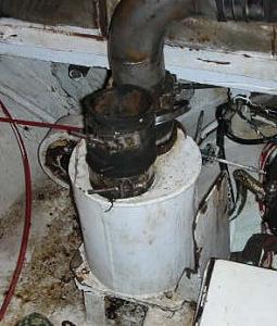
Here is a picture of one I removed from a Steel 43ft Cruiser

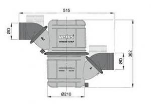
Here is another picture showing the dimensions of a waterlock from 'Vetus' 
Take the metric measurements and divide by by 25.4 -- gives a height of some 15" and a diameter (width) around 8 1/4"
The internal volume of the Vetus is around 800 cubic inches.
John, another volume 'guesstimate' would be that of your 10" x 10" Waterlock to = 780 cubic inches.
Therefore it might be useful to consider replacing yours with a 'Vetus'
Richard
__________________

|

|

|
 10-11-2010, 02:38 PM
|
#4
|
|
Admiral
Join Date: Oct 2004
Posts: 3,067
|
Hi John,
Here is a picture showing how the 'Vetus' waterlock can be fitted to most situations :

The upper and lower half can be swiveled so the that inlet and outlet pipes can be pointing in any direction. The pipes can also be swiveled to suit most configurations.
Richard
__________________

|

|

|
 10-11-2010, 03:53 PM
|
#5
|
|
Moderator
Join Date: Jun 2007
Home Port: Washington DC
Vessel Name: SV Mahdee
Posts: 3,236
|

The minimum size of waterlock needed can be calculated based on the volume of water your exhaust hose could hold (that hose being between the waterlock and your boat's transom or where ever the exhaust exits the boat. The concept is that if that hose were completely filled with seawater which all drained into your waterlock, none of it would back up into the engine. Then, when sizing, add a bit of size for "insurance" measure. So, multiply the inside diameter of the hose by itself/4 and then multiply by pi (that is diameter x diameter/4 x 3.1415) and then multiply that number by the length of the hose. Work in inches for length of hose and for diameter so you'll end up with cubic inches needed. Then, you can look at the size of various waterlocks to make sure they are larger than your minimum needed.
I know many boats have waterlocks much smaller than the above calculation, but that is how we sized ours (plus a bit of size for good measure).
The most basic of waterlocks (from the early 20th century) is a pipe from the engine entering the bottom of a cylinder and going "up" inside the cylinder about 3/4 the height of the cylinder. The exhaust exits this pipe vertically, showers down into the cylinder which has another pipe "take off" at its bottom which goes to the exhaust thru-hull. One can fabricate a waterlock like this very easily. Modern waterlocks don't share this design, but that is the basic one and if you ever had to fabricate one in a third world country with no access to Vetus or other parts, you could.
Good luck! 
|

|

|
 10-25-2010, 08:13 PM
|
#6
|
|
Lieutenant
Join Date: Jan 2005
Posts: 97
|
Sorry about the bad description
The unit for the Perkins is a vertical axis cylinder, 11.5 inches high and 12 inches diameter. The inlet is into the side of the cylinder about 3/4 of the way up, and the outlet is from the top of the cylinder with its centreline about 3 inches from the edge and nearly opposite the inlet pipe. Both inlet and outlet are 3.5 inches diameter.
That for the Onan generator is also a vertical axis cylinder, 8 inches high and 8.5 inches diameter. The inlet pipe is about 1/3 of the way up the side, and the outlet is from the top with its centreline about 3 inches from the edge and nearly opposite the inlet pipe. Both inlet and oulet are 2.5inces diameter.
Because of the available space in the engineroom, the rectangular versions will not fit, and nor will the Vetus cylindrical ones
John
__________________

|

|

|
 10-25-2010, 09:29 PM
|
#7
|
|
Moderator
Join Date: Jun 2007
Home Port: Washington DC
Vessel Name: SV Mahdee
Posts: 3,236
|

Suggest you simply take a dimensioned drawing of what you have to a fabricator and have one made up in stainless steel. It is very likely that yours does not have anything fancy going on inside other than perhaps a single baffle. Many marine fabricators have made these before--is there not a fabricator near you? There are illustrations/drawings of the interior of the cylindrical ones in the Vetus catalog and you can likely have similar fabricated. Those do not have the water cooling benefit that the "old style" one I described has but are less prone to failure.
You may also be able to substitute an exhaust gas/ cooling water separator (Vetus makes one) in place of your waterlift muffler. These are used frequently on generators and have different space requirements (and different exhaust/plumbing) which might work for you. Vetus has all dimensions in their catalog. After reviewing information on the Vetus website regarding waterlift mufflers and their installation, you may find that you can re-design the location to one which is suitable to a standard waterlift muffler. I'm not advocating Vetus as the only brand that you might use, but they do have a tremendous variety of standard waterlifts. They can also fabricate something to fit your space if you just cannot find a local fabricator or a standard waterlift that will work for you.
Warm regards,
|

|

|
 10-25-2010, 11:36 PM
|
#8
|
|
Admiral
Join Date: Oct 2004
Posts: 3,067
|

Quote:
Originally Posted by steelfan

Sorry about the bad description
The unit for the Perkins is a vertical axis cylinder, 11.5 inches high and 12 inches diameter. The inlet is into the side of the cylinder about 3/4 of the way up, and the outlet is from the top of the cylinder with its centreline about 3 inches from the edge and nearly opposite the inlet pipe. Both inlet and outlet are 3.5 inches diameter.
That for the Onan generator is also a vertical axis cylinder, 8 inches high and 8.5 inches diameter. The inlet pipe is about 1/3 of the way up the side, and the outlet is from the top with its centreline about 3 inches from the edge and nearly opposite the inlet pipe. Both inlet and oulet are 2.5inces diameter.
Because of the available space in the engineroom, the rectangular versions will not fit, and nor will the Vetus cylindrical ones
John
|
Hi John,
Good advice from Brenda - to add little more :
If you get new ones fabricated, remember that the weakest part of the stainless type is the weld. It is nearly always the welds that leak! This is because the wrong type of welding rod/wire has been used, often 304 on 316 stainless sheet, the 304 corrodes with the hot salt water and steam passing through the lock. If you take your existing waterlocks to a stainless steel fabricator, have them grind off the weld around the top of the cylinder so that they can examine the wall thickness - if OK, they can replace the top and reweld all welds with 316. I have done exactly that successfully.
Good luck!
__________________

|

|

|
 11-06-2010, 01:28 PM
|
#9
|
|
Lieutenant
Join Date: Jan 2005
Posts: 97
|
Thank you all for the advice. I shall try to get mine rewelded and stand over them to ensure 316 is used - they were welded in Grenada about 6 months ago (said to be using 316 rod, but I was not able to check that) and have failed at the welds
John
__________________

|

|

|
 11-06-2010, 06:40 PM
|
#10
|
|
Admiral
Join Date: Jul 2004
Posts: 2,098
|
FWIW, Grenada was our least favorite island, we thought the locals who were involved in "yacht service" were just a bit too greedy and dishonest for our taste. Beautiful island, though, and the people away from the docks were very nice.
__________________
|

|

|
 |
|
Currently Active Users Viewing This Thread: 1 (0 members and 1 guests)
|
|
|
 Posting Rules
|
You may not post new threads
You may not post replies
You may not post attachments
You may not edit your posts
HTML code is Off
|
|
|
|
 Recent Threads
 |
|
|
|
|
|
|
|
|
|
|
|
|
|
|
|
|
|
|
|
|
|
|
|


 Linear Mode


